Home › Unlabelled ›
Star Delta Circuit Diagram Its Controls / Star Delta Starter Control Circuit Diagram With Timer - Wiring of star delta starter with timer control panel.
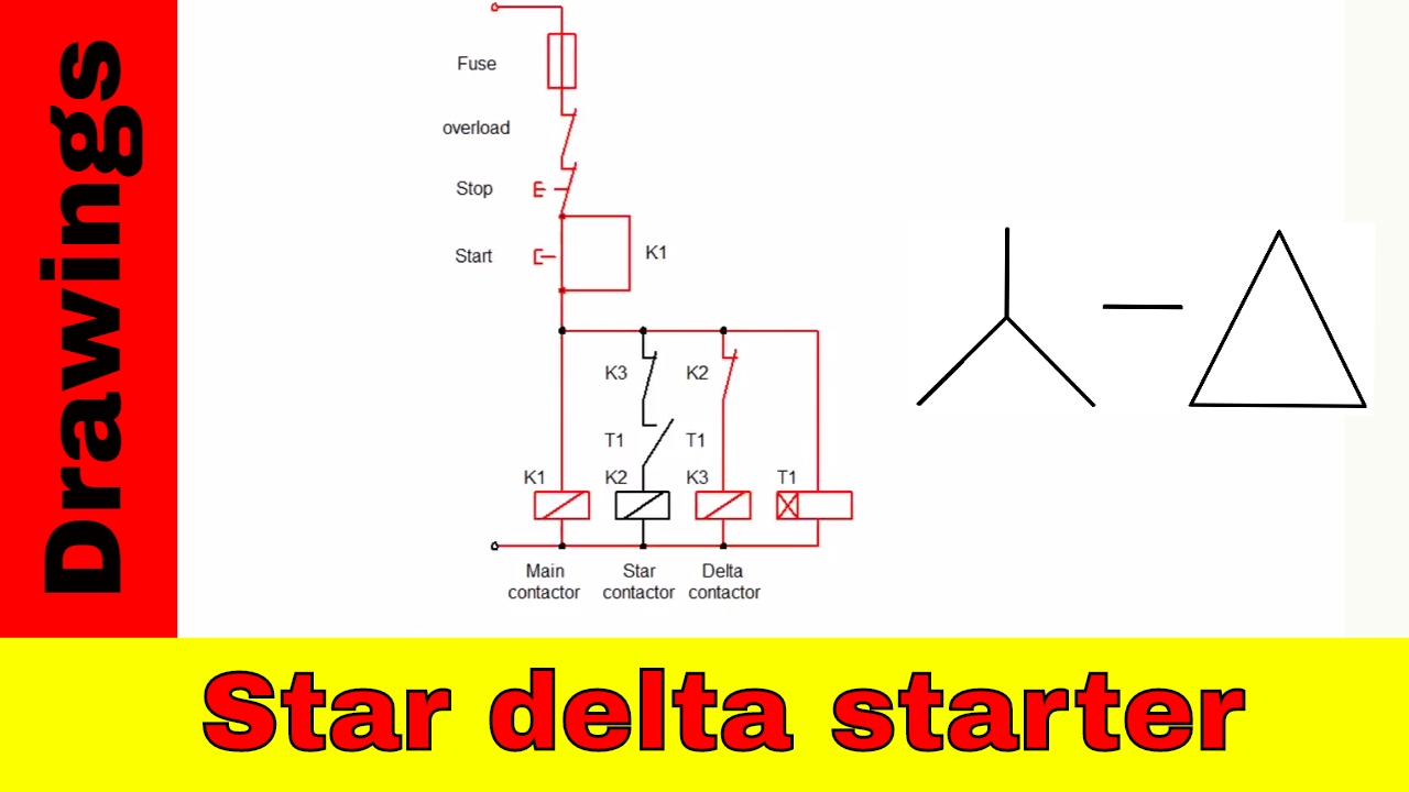
Star Delta Circuit Diagram Its Controls / Star Delta Starter Control Circuit Diagram With Timer - Wiring of star delta starter with timer control panel.. First, see the below diagram carefully to easily understand the star delta starter diagram. I know how this circuit works. The star delta starter is a very common type of starter and is used extensively as compared to the other type of starting methods of the induction motor. I'm going to use the old red yellow blue colour coding for the phases simply because i then we take a second contactor, which will be used for the delta circuit, and feed our three phases into this. Stationary contacts, and the circuit gets completed.
Why star delta become common starter of motor control? Delta connection is also known as mesh connection because its structure is answer: I know how this circuit works. Wiring diagram of star delta starter with timer. The control diagram for star delta starting of three phase induction motor for forward as well as reverse direction 10 is shown below in fig.1.
Star delta wiring diagram Apk Download latest android ... from cdn.apkmonk.com S1 = 'on' push button k1 = line contactor k2 = star contactor k3 = delta contactor k4 = star delta timer (7pu60 20) control circuit for push button control f2 = overload relay (momentary command) f1. A star delta starter is a type of reduced. Wiring diagram of star delta starter with timer. Star delta starter control circuit diagram ! Star delta starter wiring diagram, this post is about the main wiring connection of three phase motor with star delta starter and control wiring diagram of 1 mccb circuit breaker 3 magnetic contactors 3 phase motor thermal overload relay / electronic overload relay ocr an on daily timer (8 pin timer. Interlock switches are connected between star and delta contactors of the control circuit as a safety measure so one can't activate delta contactor without deactivating star contactor. Star delta starter control circuit wiring diagram consist timer, push button for start and stop. Delta connection is also known as mesh connection because its structure is answer:
Motor contactors are controlled by using plc.
The star delta starter is a very common type of starter and is used extensively as compared to the other type of starting methods of the induction motor. Star delta wiring diagram from the motor control warehouse. Plc program for star delta starter. The main circuit breaker serves as the main power supply when star main contactor (km1) close its connect motor connects on star and it's connected in star until the control circuit above also provides two interrupting contacts to shutdown the motor. In this section we will convert star formation of resistances to delta formation resistances. Star delta motor control power circuit. It is because this starter have a simple circuit diagram,low cost. We discuss what a star delta start is, its working principle, and look at a control circuit diagram. After some time motor attain 90% of rated speed and timer circuit switch starter from star transition state to delta state, full line voltage gets applied to motor and motor continues to rotate at its full speed. The power circuit diagram and control circuit diagram of an automatic star delta starter are explained below. Why star delta become common starter of motor control? 58% of the starting current reduced. A simple explanation of star delta starter.
In this article, we are going to discuss why star delta starter is preferred, circuit diagram, working principle, and application. I'm going to use the old red yellow blue colour coding for the phases simply because i then we take a second contactor, which will be used for the delta circuit, and feed our three phases into this. From here we connect our phase 1 to. As a result, a stator. Star delta starter wiring diagram, this post is about the main wiring connection of three phase motor with star delta starter and control wiring diagram of 1 mccb circuit breaker 3 magnetic contactors 3 phase motor thermal overload relay / electronic overload relay ocr an on daily timer (8 pin timer.
Star-delta starter control and power circuit diagram ... from i.ytimg.com We can now solve simple series, parallel or bridge type resistive networks using kirchhoff´s circuit laws. Star delta starter control circuit wiring diagram consist timer, push button for start and stop. We will do this by finding equivalent resitances in place of. Once the timer reaches the specified time, it activates the delta contactor to close its contact while at the same time disconnecting the star contactor. I'm studing one control circuit diagram and need your help. In this article, we are going to discuss why star delta starter is preferred, circuit diagram, working principle, and application. Nevertheless, curry out of star/delta starter control circuit on synchronous and induction usually want additional exertion and efforts and it was not relaxed in this paper, there is a providing for simulation, circuit diagram and communication for star/delta starter control circuit by plc and its result on. 58% of the starting current reduced.
From here we connect our phase 1 to.
I'm studing one control circuit diagram and need your help. In this section we will convert star formation of resistances to delta formation resistances. I'm going to use the old red yellow blue colour coding for the phases simply because i then we take a second contactor, which will be used for the delta circuit, and feed our three phases into this. Delta connection is also known as mesh connection because its structure is answer: Stationary contacts, and the circuit gets completed. A simple explanation of star delta starter. Wiring diagram of star delta starter with timer. Interlock switches are connected between star and delta contactors of the control circuit as a safety measure so one can't activate delta contactor without deactivating star contactor. Star delta motor control power circuit. Power circuit of star delta starter. From here we connect our phase 1 to. When the motor picks up the speed, about 80 percent of its rated speed, the switch s is immediately put into the run position. The power circuit diagram and control circuit diagram of an automatic star delta starter are explained below.
I'm studing one control circuit diagram and need your help. When the motor picks up the speed, about 80 percent of its rated speed, the switch s is immediately put into the run position. Wiring diagram of star delta starter with timer. From here we connect our phase 1 to. I'm going to use the old red yellow blue colour coding for the phases simply because i then we take a second contactor, which will be used for the delta circuit, and feed our three phases into this.
star delta starter control diagram explain animation video ... from i.ytimg.com The equivalent resistance between node 1 and node 3 in the star connected circuit is r. A simple explanation of star delta starter. Wiring diagram of star delta starter with timer. It is because this starter have a simple circuit diagram,low cost. As a result, a stator. Power circuit of star delta starter: Why star delta become common starter of motor control? Stationary contacts, and the circuit gets completed.
Stationary contacts, and the circuit gets completed.
A star delta starter is a type of reduced. Stationary contacts, and the circuit gets completed. Power circuit of star delta starter: Wiring diagram of star delta starter with timer. Delta connection is also known as mesh connection because its structure is answer: Once the timer reaches the specified time, it activates the delta contactor to close its contact while at the same time disconnecting the star contactor. First, see the below diagram carefully to easily understand the star delta starter diagram. Star delta wiring diagram from the motor control warehouse. Interlock switches are connected between star and delta contactors of the control circuit as a safety measure so one can't activate delta contactor without deactivating star contactor. It is because this starter have a simple circuit diagram,low cost. As a result, a stator. The equivalent resistance between node 1 and node 3 in the star connected circuit is r. The main circuit breaker serves as the main power supply when star main contactor (km1) close its connect motor connects on star and it's connected in star until the control circuit above also provides two interrupting contacts to shutdown the motor.